
Pic1: Keyboard
What a great opportunity to experiment I thought! I always wanted to make my own midi device and here was a chance. So I decided to make a midi keyboard.
Below is the video of the final result...
For those interested there is a second part of the project here where we add Velocity and After touch to the keyboard.
>>> UPDATE: Thanks for your interest! MIDI Kit available here! <<<
First thing during the keyboard autopsy I've got rid of all the intestines. The keyboard was implemented pretty much on a single chip so I took out the main board which left toy with keyboard/keys part only and plenty of space to keep my PCB inside.
As you see from the picture keys are using simple On/Off circuit for each note so I was not expecting to make a velocity sensitive keyboard. In future posts I'll talk how volume/velocity and other expression can be added to this project so stay tune... :)

Pic 2: Keys PCB
Ok, we have got a keys now we need something to read when keys being pressed and released. After that event needs to be interpreted and passed to other device as PC or MIDI enabled device that will hopefully do something useful as play music or make some noise (that no one except yourself will enjoy... :)) We need a micro-controller. I've chosen to use Arduino board that uses ATMEGA based - programmable micro-controller. Arduino comes with IDE and number of examples. Arduino is one of many ATMEGA variants and there are plenty of compatible Arduino boards so feel free to use any other compatible device. The Arduino board usually comes in a kit with a breadboard, patch wires, resistors, sensors, LCD, LEDs, push buttons and other stuff that is cool to play with and experiment. I've got this one and found everything I needed so far:
https://www.sparkfun.com/products/11236
So coming back to Keyboard that we need to read. Keyboard has 32 notes/keys that can be pressed or released simultaneously. We are planning a polyphonic device so we need to make sure our controller able to recognize more than one key pressed at the same time. Actually it will allow all 32 keys to be pressed at the same time which is likely would never be required unless you got a monkey playing the piano... (I'll demonstrate it in my video :)). Casio Keys PCB (Pic1) uses scan matrix of 8 notes organized in 4 groups. 8*4=32 notes. In scan matrix terminology it is 8 columns and 4 rows. In order to read notes we need to scan 8 columns one by one and read 4.
If we use pure I/O of the Arduino we would require 12 I/O(s) which is more then we can afford. Instead we will use shift register controller that will use slightly less I/O(s) - 7.

Pic 3. Keys scan matrix 8 Columns (Red) and 4 Rows (Yellow)

Pic 4. Keys PCB schematic. Columns (red) and Rows (yellow).
To scan PCB we will use Parallel-out shift register technique. A very detailed description of Parallel-out shift register and other techniques available at below link:
http://www.openmusiclabs.com/learning/digital/input-matrix-scanning/shift-out-mux/
In short Parallel-out is one of the effective scaning techniques available in terms of number of Digital I/O used, scan time and response time.
Parallel-out shift register was implemented using 74HN595 shift-register chip that was available in the Arduino kit that I bought. Here is a good tutorial on 74HN595 if you would like to understand the principles behind the work of the chip:
http://www.arduino.cc/en/Tutorial/ShiftOut
I've end up with relatively simple schematics below:

Pic 5: Controller schematics
As you see connector from Controller schematics J1 has 8 columns and 4 rows that are matching to the existing keyboard schematic.
Assembly List
| Label | Part Type | Properties |
|---|---|---|
| Arduino1 | Arduino | processor ATmega; variant Arduino UNO R3 |
| J1 | Generic female header - 12 pins | package THT; hole size 1.0mm,0.508mm; row single; form ♀ (female); pins 12; pin spacing 0.1in (2.54mm) |
| MIDI OUT | DIN-5 jack (MIDI) | package THT; form jack (female); pins 5 |
| R1 | 10k Ω Resistor | package THT; tolerance ±5%; bands 4; resistance 10kΩ; pin spacing 400 mil |
| R2 | 10k Ω Resistor | package THT; tolerance ±5%; bands 4; resistance 10kΩ; pin spacing 400 mil |
| R3 | 10k Ω Resistor | package THT; tolerance ±5%; bands 4; resistance 10kΩ; pin spacing 400 mil |
| R4 | 10k Ω Resistor | package THT; tolerance ±5%; bands 4; resistance 10kΩ; pin spacing 400 mil |
| R5 | 220 Ω Resistor | package THT; tolerance ±5%; bands 4; resistance 220Ω; pin spacing 400 mil |
| U2 | 74HC595 | package DIP16 [THT]; type 74HC595 |
If you would like to try it first below is a breadboard diagram.
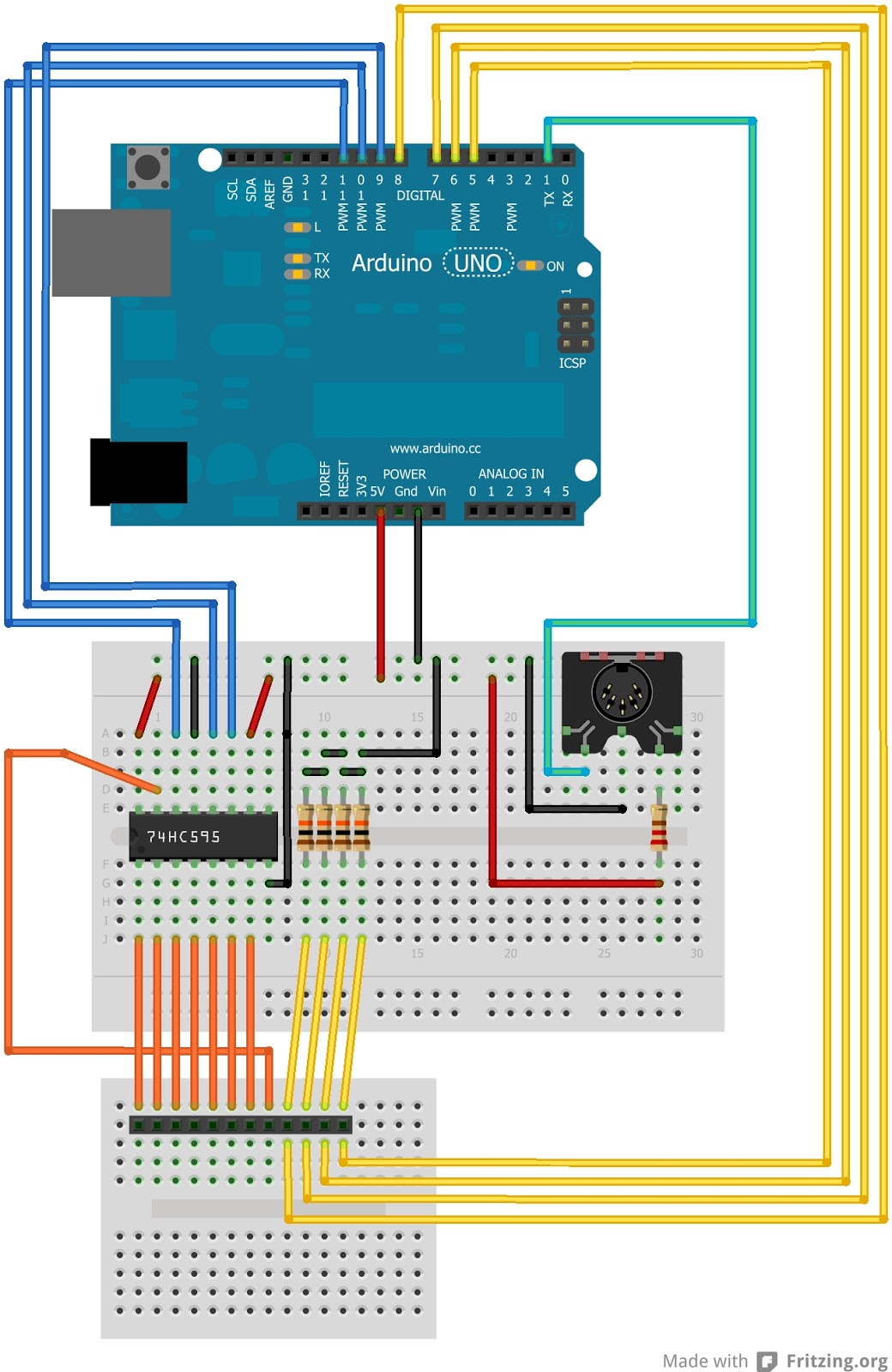
Pic 6: Controller prototype on a bread board
First controller prototype was made on the Arduino breadboard. After that controller was transferred to a Freetronics Protoshield that was meant specifically for Arduino board. The good thing about the size and the pin outs are perfectly matching Arduino and not only project will look professional but all components will fit nicely together. :)


After assembling all main components below is the working components necessary to implement a MIDI keyboard.

Pic 9: Keyboard logic components sufficient for operation.
Below is the source code for Midi keyboard. You will need to open code in Arduino IDE and upload it:
Please note you might need to re-arrange the mapping of the notes to MIDI in keyToMidiMap base you the order you wire Keyboard Rows to Row pins.

The bottom of the keyboard casing with Arduino shield fixed with silicon glue and holes made for connectors. As well you see the container that will hold different MIDI enabled sound modules.

Casing closed and final look without sound module.

Below is Yamaha QY-100 sound module fits nicely.

Hope you enjoyed it!... :) Happy tinkering!
Follow to the second part of the project here where we add Velocity and After touch to the keyboard. And here is the third part on how to enable USB connectivity to your PC.
hi there! Thanks for the video and information.
ReplyDeleteI'm gonna built it but i got a question: I've 54 key and the source code written as 32 keys so which parts i should change in code?
If you have more keys you will need to alter Schematics a bit. It could mean more column/row(s) and base on that you either will have to put one more 74HC595 in serial with existing and have say 16 columns 4 rows (which would allow you to scan 64 keys). This would alter schematics.
DeleteOr you may get away with current with minor alteration of schematics if you have say 8 rows and 8 or 7 columns (that would mean you will have to use more I/Os on the Arduino).
What sort of keyboard you got? do you know how the scan matrix organized on it - column/rows?
Me pasa lo mismo y nose como leer la matriz
DeleteThis comment has been removed by the author.
ReplyDeleteMy keyboard doesn't have any organized matrix in it. I bought it in local bazaar for a few bucks and it was ruined when i get it..I think i'm gonna make it the matrix but need some help at that point. I just count, it's got 61 keys in total. So what should i do could you please put me to the right direction? 16x4 or 8x8 which one is the better for me?
ReplyDeleteHi Depending on how much you want to hack with the original schematics. The easiest option and minimal changes would be to implement 8 x 8 but then you will use up all your Digital I/O. If you planning to use Digital I/O for anything other sensors or buttons then you either will need to put one more 74HC595 to scan matrix and reduce I/Os used or go with Arduino Mega as it has more I/Os in total.
DeleteIn any way you will need to find out how your keyboard scan matrix PCB organized. You will need to find columns and rows. Usually it is easy to do just by measuring resistance between two wires on the matrix while pressing piano keys. You can shoot email to codetinkerhack@gmail.com with your keyboard Keys PCB pictures and I'll try to suggest what to do...
Thanks for response. You helped me a lot! i'm gonna make my own scan matrix. So i'll make 8x8. Which parts of source code i have to change for 8x8 matrix?
ReplyDeleteHi, no problem. you will need to make PCB on Pic3. Schematics of it is on Pic4. I would say you should probably have it in the keyboard that you bought. Making it is quite a task requires precision. Unless you have some ideas on how to make it easy. But if you have it already and just would like to wire it to the project you need to double the Pic4. you will end up with 4 extra rows highlighted in yellow (currently 4 will be 8). Then same with Breadboard - will increase 4 rows to scan extra 32 keys (total 64). You can use remaining Digital I/Os on the Arduino 4,3,2,0.
DeleteIn code you will need to modify keyToMidiMap and add definition to map extra 32 keys. and in loop() { you will need to scan extra 4 rows: int groupValue4 = digitalRead(row4); repeat for 5,6,7,8 rows. Thats about all. :)
Great post! I've always wanted to do something like this. I'll have to give it a try.
ReplyDeleteGo for it mate! :)
DeleteHi there, thanks for your info on the MIDI keyboard. Im just getting in to Arduino whats the max key input can the Arduino / Atmega handle, was looking for 88 keys or full 128. thanks
ReplyDeleteHi, your welcome. I would suggest to use some sort of scan matrix with Arduino. You need to find out how the keyboard keys matrix organized first then consider how you going to read it with arduino. I suggest to read questions from Gorkem. He has similar considerations. If you have further questions please let me know.
DeleteThanks a lot. I changed the diodes polarity and it's worked. So i think the schematics is wrong or i don't know how to read diodes polarity. The lined side of diode is the lined side of diode visualization in the schematics right? If it's so, the schematics is wrong.
ReplyDeleteAnd one more thing; When i done with wiring etc. my code doesn't worked very well. When i push a button it sends note but when i released it sends a note again it's not cutting the note.. And a lot of notes in the background was proceeding with a little velocity. Then i used the midi library for arduino. I changed the noteOn codes according to midi library which i installed. Then it worked very well.. Maybe that problem related to my computer or arduino.. But for someone who have this problem, keep that in mind.
Thanks a lot Jen Shen. You should be proud of you for helping people, who has not enough money to buy a midi keyboard for making music or someone who just wanted to create something.. It's great behaviour, sharing your code and DIY journey..
Hi Görkem,
DeleteGlad you have succeeded! If you could please send some snaps of what you got so I could share with others to inspire them.
The polarity of diodes in diagram (that I've drown base on the keyboard pcb) was indeed wrong. I've updated the schematics now. Thanks for pointing it out! The code should be fine as it is working all the while and notes can be pressed on/off with no issues. I would be interested to understand if there was issue but I could not find any. And you are right that any MIDI library can be used. In the code I've used simple noteOn command over serial connection to demonstrate the abilities and remove relation to 3rd party library. :)
Thanks,
JenShen
https://www.youtube.com/watch?v=mLeFq4I4QS0&lc=z12mz505oljqxr4ak04cevyxaqjffr0p3ks0k
Deletehere is my video about 4 years later :)
Hi.... Excuse Me....I Am Masum From Bangladesh... Can U Kindly Help Me....? I Have A Xin Yun Xy 213 Toy Piano....I Need To Turn iT Into A Midi... But I Can't Understand Whether iT Will Work or Not...? If Works Can U Explain Me Shortly... What To Do....? I Need Ur Help..... Thnx.... For Ur Nice Covery...
ReplyDeleteHi Masum,
DeleteThe detailed instructions are right here in the article. It is however based on the Casio. I am not familiar with "Xin Yun Xy 213 toy piano" I would assume it would be quite similar to other toy pianos. So all I can say give it a go and good luck!
Hello, I am a DIYer from HK. I used to buy a 72 midi encoder program by a boarduino from here:
ReplyDeletehttp://midikits.net23.net/midi_8x9_keys/midi_8x9_keys.htm
In fact, it is a 8x9 matrix. I just wonder why he doesn't have to use 74HN595 as shift-register and still can provide 9 rows. Is that because of he use Analog input as Digital input?
Here is the schemetic diagram:
http://midikits.net23.net/midi_8x9_keys/keys_8x9_switches.gif
I would like to learn to program arduino to make this 8x9 matrix keyboard. Do you have any ideas?
Regards,
Carlos
Hi Carlos, you have answered your own question. You can skip using the 74HN595 but it will utilize 8 instead of 3 I/O and you will need to borrow Analog inputs. This is not giving you any extra space to experiment. I am going to post next post on how to add expression using analog inputs. You can convert above code to use digital/analog inputs and no 74HN595 and it will work same. You just need to change scanColumns to iterate through 8 I/Os and set it HIGH/LOW on by one. The rest is about the same... And in fact the project you linked is a very common Arduino board clone as I see. You could spend 10 dollars (or less) and build one yourself. :)
DeleteHi Jen,
ReplyDeleteThank you for this great article. I have an old M-Audio oxygen 61 that has 61 keys and 14 pins coming out. I am assuming I need to get two 75HN595's, but am not quite sure how to implement them.
Thanks a lot,
Daniel
Hi Daniel,
DeleteAssuming more or less common velocity sensitive keyboard design (which I believe your keyboards is) I can't figure out maths here. If its 61 keys it should be something multiple 8 equal or greater 61 (as 61 is not multiple of 8) say for non-velocity sensitive keyboard would be 8*8=64 and so you will need to have either 16*4 or 8*8. In your case as keyboard is velocity sensitive I would expect it to be 16*8 likely. Meaning you will have 16+8 pins... 14 pins is 8+6 wires and 8*6=48 notes (and there is no velocity sensing considered). Probably you will need to verify your keyboard keys PCB to understand how the contacts traced. Should be something similar to Pic 4 (but double the Rows for velocity sensing).
If you would like to make velocity sensitive keyboard you will need to modify schematics and code. I've done similar experiment in second article of the series but I have not used standard velocity sensing implementation.
I'd say you will need to pick likely 2 of the shift registers and you will have double the rows 8 which you could route to digital/analog Inputs and you could use second article code and modify it a bit to read time between note down start/down complete events and translate this to velocity.
Good luck!
Hello!
ReplyDeleteSo, I've followed everything like it's here and I manage to get all 32 keys working.
It seems that the order of my matrix is the same as yours, but I have 2 problems:
- The first is that all notes are out of order and position, this problem I think I can fix in the code.
- The second is that I can't press many of the keys at the same time, just a few work at the same time.
I want to know if I could fix the second problem by code, or if it could be a problem in my circuit.
Do you have any clue about this?
Thank you in advance!
I've also noticed something, my keyboard doesn't have diodes! Are they REALLY necessary?
ReplyDeleteHI Eric,
DeleteYea, that's likely why only several keys are registered instead of many (actually all can be pressed at the same time and should work). Diodes in the matrix are important. You will need to add those otherwise scan matrix would not work.
Cheers,
JenShen
I don't know how I'm gonna add the diodes, the board that is used by the keys is like yours, but it doesn't have the diodes or the space to solder them.
DeleteSo, if I add them I'm gonna be able to press more than one key at the same time?
What kind of diode should I buy?
Thank you!
Hello, I'm having a lot of problems 'cause of the diodes, since the pcb for the keys doesn't have them, I was trying to do it in another way, which was remaking the buttons with aluminum paper, but it won't work, the solder doesn't stick to aluminum paper well.
ReplyDeleteWould it work if put a diode for each column instead of a diode for each key? I think it's the only way that would be able to do it, but I don't know if it will work.
Thank you in advance...
Hi Eric,
DeleteYou must use diodes according to schematics Pic 4.
Any diodes similar to 1N4004 or RLR4004 will do. I suggest to get couple and verify it by prototyping on the breadboard. After confirm working - get set of diodes and apply it to the board. It is MUST to use diodes in the scan matrix.
Good luck,
JenShen
Cool, I'll probably have to remake the board, this one won't work. I bought 1N4007 diodes, those were the only diodes I could find, the seller said they are almost the same...
DeleteI'll, I'll try to figure it out here, thank you very much!!!
Not necessary to use 1N400x series because they are bigger in size and more expensive. In that case you can use the 1N4148 the diode that all use it.
DeleteHi, I think I understood how to make MIDI my matrix keyboard, but if I don't want to generate MIDI to control other synths, but generate voltage to control a VCO via ARDUINO( keepeing the same connections with ROWS and COLS)? What kind of sketch I need? thanks so much..Simon
ReplyDeleteHave you considered controlling it via Arduino analog output via PWM or generic digital to analog converter? Sketch would be slightly simpler instead of sending notes to midi you would call function that controls analog output to a voltage controlled synth.
DeleteThank you Jen for a clever project, I've built it successfully to this stage and will eventually add the velocity feature. My keyboard came from an old lowrey organ and already had the diodes and matrix, as it is 3 octaves I increased the rows to 4 and adjusted the code to suit, it all works very smoothly.
ReplyDeleteMy aim before adding velocity is to add a hold pedal as I think this is essential for serious use, I think the easiest way is to make a switch between 5v and one of the spare inputs, this I can do but I have no idea what code I need to add, have you had any thoughts on this? thanks again for a very informative project.
Good to know you succeeded in adding midi to old Organ(?) Sounds awesome! :)
DeleteHold pedal is a sustain pedal if I understand you correct? You will need to do some small add on to the code for that. Hold pedal will provide on/off events to one of the digital I/Os as I understand and will send midi sustain messages on specific channel. (for midi message specs check here: http://www.midi.org/techspecs/midimessages.php)
So the function you need to add is quite simple:
global vars:
int FREEDIGITALPIN = ...;
int prevSustainState = 0;
set another pin for input in setup() {
...
pinMode(FREEDIGITALPIN, INPUT);
...
}
in loop()
{
// before for loop
int sustainValue = digitalRead(FREEDIGITALPIN);
if(sustainValue && prevSustainState == 0) {
// send midi message to notify sound module about sustain pedal on - base on the midi specs or effect your sound module supports send MIDI bytesequence here
}
if(!sustainValue && prevSustainState == 1) {
// send midi message to notify sound module about sustain pedal off - base on the midi specs or effect your sound module supports send MIDI bytesequence here
}
// before for loop
Many thanks, I will try it and let you know how it goes.
DeleteHi there,
ReplyDeleteMany thanks for this hack! I've identified that I have a 61 key, 8x8 keyboard - how can I use another shift register for the rows to free up digital IO pins?
Thanks again!
Jonathan
hello ,
ReplyDeletethis sounds brilliant
so can u please tell me which board to use for CASIO SA 21
From the first look at CASIO SA 21 you should be able to use the instructions in this post.
Deleteand can u plz tell me the possibilities
ReplyDeleteof making a new unit (without keyboard keys offcource) n ship it to me for obviously some money , n furthur i can just solder the complete kit to my 32 key's 12 row wire band
I am planing to make a kit for it as long as there is enough interest. In the mean time may be you could suggest what sort of money would you pay for it in the private message: codetinkerhack at gmail dot com and if you could explain your interest to understand the potential customers.
DeleteHello Jen!
ReplyDeleteI find your project amazing! I have been searching the web for months and your tutorial is the most clear and complete I have found so far. You explain everything providing parts lists and useful links.
Like other people above, I also intend to build a 61-key keyboard. Unfortunately, I can't get hold of any used or broken keyboard, so I decided to experiment a little bit with plain switches... id est: Tact Switches! My plan is to lay down all the switches on a wooden surface. Each switch will be on its corresponding position like in an actual keyboard. So this part of the build is (kinda) sorted out.
Another issue that needs to be resolved is the multiplexing and I/O reduction using shift registers. As far as this is concerned, I found this useful instructable presenting a similar project. On step 9 there is a link to all the necessary files for the project. The guy is also offering a schematic but it is designed for 2 keyboards of 61 keys each. I asked him in the comments about the necessary changes for a single keyboard, but it wasn't really clear what should be done... So... My question is: Should I use his schematic (that, I believe, does not require any multiplexing) or should I use your design and multiplex the switches to a 8X8 matrix? Keep in mind that I have lots of 74HC595 ICs in handy (more than 8) and lots of diodes as well... So, as far as the components are concerned there is no problem at all. I would just like to know which option is better: Lots of shift registers, no multiplexing, no diodes OR less shift registers (2 if I am right), with multiplexing and diodes. For me it's the same (meaning that I don't mind if I put more effort for better results).
Of course, there is anothere problem. That is the changes that have to be made to the arduino sketch. I think that if I use your design-concept, then the change will be minor. Either way keep in mind that if we finally decide on the design, I will need some guidance with the source code.
Thank you in advance,
Sotiris.
Τι εγινε Σωτηρη βρηκες καποια ακρη με τα σχεδιαγραματα?
Deleteψαχνω και εγω ( εχω ενα με 76 πληκτρα και ειναι χαλασμενο )αλλα θελω κατι ετοιμο, εχω βρει αυτον τον τυπο απο Αγγλια https://www.midikits.net/index.htm
Το έχω παρατήσει το project για να σου πω την αλήθεια...
DeleteΑλλά θυμάμαι ότι κάτι είχα καταφέρει και νομίζω ότι είχα χρησιμοποιήσει μόνο 2 shift registers.
Αν βρω χρόνο να ασχοληθώ ξανά, θα σου πω.
Edit: I think that my assumption about the number of s.r (shift registers) required if your diagram is used might be wrong... I am not sure though... Anyway... The question remains the same. What is the best way to build a 61-key keyboard? I came up with an alternative solution for multiplexing: 4X16. The four columns will be connected directly to the 4 digital pins of the Arduino and the sixteen rows will be scanned by two 74HC595 ICs. The serial data output pin from the first s.r. will be connected to the serial data input pin of the second s.r. (pin 9 to pin 14). I believe that this will actually work!
ReplyDeleteBUT! I am still not sure what has to be done with the code... (Well, obviously it should be altered).
I am looking farward to your answer,
Sotiris.
Hi Sotiris,
DeleteI will prepare a how-to build 64 key keyboard. Will update the post - stand by please.
Cheers,
Jen
Thank you for your response! Can't wait for the update!
DeleteHow's the update going?
DeleteHello Jen Shen
DeleteThank you for your work which allowed me to make my 61-key MIDI keyboard that works perfectly.
the keyboard is a recovery of an old organ Honner stamped in 8 * 8
I just send you the diagrams and your modified code if it can be some util.
Excuse my language (google translation from French to English)
Could you please send the code to me, too?
DeleteThank you in advance!
Hi Guys,
DeleteI've prepared small post on how to make 64 keys keyboard:
http://www.codetinkerhack.com/2013/12/how-to-build-64-keys-midi-keyboard.html
Hope this helps! And Claude if you could please send me any links to your blog post - I'll add a link to it. It is nice to see it is something useful and inspires others!
Thanks,
JenShen
Check out MIDI Kit: http://www.codetinkerhack.com/2014/08/midi-kit-add-midiusb-interface-to-old.html
DeleteHi Jen, Great tutorial! ! have a couple of newbee questions :-)
ReplyDelete1/ Which part of the code dictates the MIDI transmit channel?
2/ Does this code require the Arduino_MIDI_Library_v4.0 to be loaded?
Hi Phill,
DeleteYou could use MIDI library to do that. There are more features you could potentially use but for this project it was not required. In my case I've used simple Serial write commands:
void noteOn(int cmd, int pitch, int velocity) {
Serial.write(cmd);
Serial.write(pitch);
Serial.write(velocity);
}
How can we do that because I added a modulation weal but it looks it must be on the same channels to affect each other...
DeleteHi Jen, this project looks like just what I need. I'm converting a set of organ bass pedals to midi. They are not velocity sensitive and there are only 20 pedals so 20 notes needed.
ReplyDeleteWhat I would like to do is add two switches so that I can increase or decrease the octave a couple of times. I assume that to do this I'd need some code that adds or subtracts 12 to the midi note number when the switch is pressed. Is this correct?
I'm new to Arduino having just embarked on another project for a drum trigger to midi module, so my knowledge is still very minimal. Could you help a lttle and tell me if this is as simple as I think it would be and where I should adjust the code to add the switches.
I assume this would also be a nice addition for people with small keyboards too.
Regards
Hey I own a SA - 55 Casio Keyboard !
ReplyDeleteHow can it be converted into MIDI without much of the investment cost ?
How much cost,time would require to do it?
Is it easy and accurate?
Check out MIDI Kit: http://www.codetinkerhack.com/2014/08/midi-kit-add-midiusb-interface-to-old.html
DeleteHi, this is fantastic DIY project. Will you update your tutorial with velocity sensitive keyboard? Regards,
ReplyDeleteHiya Jen Shen,
ReplyDeleteWow, great article, just what i have been searching for. M-Audio released a series of midi USB comtrollers with a pretty attractive set of features, yet the one ugly feature was a terrible propensity to randomly and pretty permanently develope what is known among users (sufferers?) as the "blue-screen of death" due to the unit's small lcd screen going blank and blue, as well as all USB traffic ceasing completely. Long story short, dead comtroller, and absolutely NO love from M-Audio. But as a good friend once said to me, "consider the problem an opportunity." And so I have. Using varioius caches of information across the web, i have decided to do the whole "bionic-man groove," and build it better, stronger etc than it was before, and hopefully, create a new path to satisfaction for myself and the MANY other m-audio owners who where laft high-and-dry.
That said, Mine is an M-Audio Axiom 25. It was designed with semi-weighted (pseudo-velocity) keys, resulting in a matrix of 50 "switches," virtually identical to those in your example keyboard above. The first 25 for keyON and the second for KeyOFF. The matrix would be a simple 5X10 or some equally simple arrangement but the twist is it is actually 5 "grounds" and 12 "highs." The 1st "high," actually scans the notes (C1,F#1,C2,F#2, and the "x-tra" top and final note C3), all others consist of 4 notes equaling 25 notes, and 50 "switches," 2 for each key. The entire matrix is actually already wired through an Atmel MCS-51 compatible 40-pin dip model AT89S52, and the output of the microcontroller is then dumped to another chip which also habdles the usb interfacing, and takes input from variois other switches in the form of 8 drum pads, various knobs, and a pair of wheels (pitch etc) and outputs for lcd and other needed items EG. midi data etc.
Now I am hoping to move carefully and in phases to reach my goals, and would like to begin by taking the matrix data from the existing Atmel controller for the project, and passing it along to an Arduino Uno I have bought specifically for this purpose, implementing your procedures for using the midi code and passing it additionally to the USB HID protocol on the Same Ardiuno UNO so that i can habe a firm base from which to build. whew! I hope I have not lost ya yet!)
I need to know, assuming i can either find a way to create a "dump," of the existing AT89S52 controller's code, or rewrite it to suit my needs, do you see any gross tactical errors in my overall scheme, or does it sound, well, ....sound? From my research, it looks to be feasable and if the AT89's ability to handle the matrix is workable, this leaves lots of exciting possibilities for the remaining I/Os on the 'duino to handle the wheels, knobs and pads for my use!
Thoughts, ideas, opinions? I thank you in advance both for sharing your own MAD-skills, and time, as well as any assistance you can provide.
Dan in Chicago, U.S.
Hi Dan,
DeleteUnfortunately i do not know much about AT89S52 - it does look like capable of handling matrix as you described. What you will need to find out is protocol/pinout that it outputs in order to interface/read it in Arduino. I think its going to be a great project to try. Good luck!
JenShen
For those who are interested MIDI Kit available to enable your MIDI projects!
ReplyDeletehttp://www.codetinkerhack.com/2014/08/midi-kit-add-midiusb-interface-to-old.html
Parabéns pelo projeto ,seria possível esse projeto via radio?( sem fio (xbee) os códicos mudaria?
ReplyDeleteHow hard would it be to add pitch bend and a few other potentiometers to this code? Also would it be possible to make Arduino output corresponding CV/Gate with a PWM pin, and two square waves on separate digital pins to make a crude oscillator?
ReplyDeletekeyToMidiMap[8] = 56;
ReplyDeletekeyToMidiMap[1 + 8] = 49;
keyToMidiMap[2 + 8] = 50;
keyToMidiMap[3 + 8] = 51;
keyToMidiMap[4 + 8] = 52;
keyToMidiMap[5 + 8] = 53;
keyToMidiMap[6 + 8] = 54;
.........................
can you explanation the "keyToMidiMap[5 + 8] = 53" and others similar this script? i don't understand abput this..
thanks for the explanation..
Hi Friend. Is it possible to take output via usb.?? i mean midi over usb?? please tell me i need that.
ReplyDeleteJust to mention that this excellent article has been a great source of help for building a portable midi keyboard (here is a video of my first portable piano prototype in action)
ReplyDeleteIs there a new link?
ReplyDeletedo you have schematic for this project?
ReplyDeletehttps://www.youtube.com/watch?v=ogEanMCsHO8
Verrry urgent :::
ReplyDeleteHey, i was working for own midi cheap keyboard from a month and got ur article just a week ago. I succesfully made it, thanks a lot and god bless you.
However im able to play each key with exactly the same not but i can play #chords with it. Also when i press adjacent keys the first key's (from left) note is played and the other is ignored at many places in my keyboard. :( After working so hard i didnt expected this. Well i used keyboard with 54 keys and my scanned matrix was 8col*7rows.
Please its very urgent
Thankyou for your help.
My email : lovesk689@gmail.com
I am about to embark on my first adventure into this realm. My Korg Microkey 37 has kicked the bucket. Is it possible to do something like this, but using USB as the communication medium into my PC? I feel as though I am going to have to gather resources from a few different DIY projects and see if I can apply them to my own dilemma. I'm just really glad I'm finally knocking the dust off of that old Arduino Uno I've had for like 5 years! Thanks!
ReplyDeleteHello, how can I adapt this code for a matrix keypad 4x4 like this? http://www.miniinthebox.com/it/4x4-matrix-tastiera-tastiera-module-201211270080064_p478899.html Is it possibble doesn' t use the 74HC595? Thank you
ReplyDeleteThis comment has been removed by the author.
ReplyDeleteGreat project.... but I have a doubt since Arduino UNO3 is having a USB port can I connect the keyboard to PC directly . rather than going for converting the signal to MIDI and then use a USB MIDI interface.
ReplyDeleteregards,
Alex
hey can i connect the keyboard wire directly to the arduino mega with out The 74HC595 board? if ur answer is "yes" thn what should be its code? please help me
ReplyDeleteOK!! A very good work!
ReplyDeleteI trying to con vert a toy piano keyboard but it uses resistors instead of diodes. I've reading about matrix reading but did not find how to read it. I'm very confused.
In http://i1250.photobucket.com/albums/hh526/arduinoxino/teclat_imaginarium_zpsryw8t9ac.png
I posted an schematic of toy piano keyboard.
Any suggerence?
Thank you very much!
Hi,
ReplyDeleteI was just wondering how you managed to figure out the scan matrix. I have the exact same Casio keyboard you used but when I connect a multimeter in diode check mode across two of the pins and sweep the keys I don't get anything. I would just copy your schematic but this is an excersise in learning as much as anything else. Is there something odd about these rubber dome switches I should know or am I missing something else? The keayboard is still completely intact currently, I haven't removed the keyboard from the main board since i'd like to leave the main board intact and just add MIDI as well.
Thanks
Jake
Hello there! very interesting post, i have a casio sa-21 myself, does this apply to the 21 model? I really want to give it a try.
ReplyDeleteJust read older comments, nevermind and thanks for this post :)
DeleteWill notify if it works on a 21.
hello great project.
ReplyDeleteI need add midi in my Yamaha cs01,i should do the same???
thank you